Lubrication test of metalworking fluid
March 07, 2023
There are many tests to evaluate the lubricity of metalworking fluids. Each experiment has its inherent advantages and limitations. The lubricity test can be broadly divided into three categories: one is based on simple friction or rolling behavior; The other is based on the process of metal cutting or abrasive chip generation; The last type of test includes the forming or stretching of metal sheet. Due to the complexity of the actual conditions, no test equipment can simulate the lubrication of all metal processing operations in the factory. This is why it is difficult or impossible to correlate the data on the test bench with the actual performance. Therefore, several different lubrication tests should be used to evaluate metalworking fluids. Some test methods are briefly described below. 1. Relevant test of friction surface Bench test is the most commonly used test method for evaluating the lubricity of friction process, but its value is limited compared with metal cutting and grinding. However, the evaluation of friction behavior may be meaningful for cutting and grinding when the workpiece or tool slides relative to a supporting surface. For example, the guide blade of centerless grinder is worn, and the guide block of deep-hole drill or reamer is worn. Friction experiments are very useful for evaluating stamping and drawing processes. (1) Shaft and v-block test The shaft and V-block tests may be widely recognized friction tests. Two steel blocks with V-grooves apply pressure to a rotating steel shaft immersed in liquid.
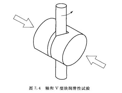
There are two different test methods for this testing machine. ASTM D3233: In order to measure the load capacity of the liquid, increase the pressure of the steel block until the steel block and shaft are stuck; ASTM D2670: The load on the steel shaft remains unchanged, and the anti-wear property of the liquid is measured as the ratchet device moves forward. The wear of the steel shaft can be measured by the number of teeth that the ratchet moves during the test. These metalworking fluids range from high oil content to fully synthetic and water at the bottom. It is worth noting that the number of teeth worn by transparent synthetic fluid with light load is the lowest, and its maximum load is equal to the maximum load of soluble oil with heavy load, both of which are 45001b. The reason for this result is that a small amount of antiwear agent is added to the synthetic fluid, which makes the light load products pass the friction test, but this does not guarantee the cutting or grinding performance under heavy load. At the same time, it is worth noting that chlorine and sulfur additives in these two soluble oils can not eliminate wear even though they increase the maximum load. (2) Four-ball machine test The three steel balls in the four-ball machine are statically placed on a cup bracket, and the fourth steel ball is on the three steel ball rotates under pressure. Based on this basic concept, there are two different test methods.
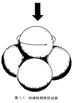
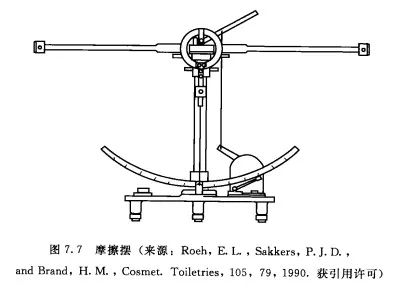
The first method is to measure the wear spot diameter, that is, under the constant rotating speed load, the wear spot size of three stationary balls is measured after the lubrication test of the four-ball machine in for a certain time (ASTMD4172). This test determines the relative wear resistance of different liquids. The second method is to measure the extreme pressure performance. During the test, the rotation speed is constant, and the load is increased until sintering occurs (ASTMD2783). D. Kirkpatrick compares three metalworking fluids, namely, fully synthetic, semi-synthetic and soluble oil, with these two technologies. (3) Friction pendulum test The friction pendulum or soda pendulum measures the friction coefficient under a certain temperature range (Figure 7.7). The pendulum shaft is supported by four steel balls, which are placed in the cup containing the test fluid. If there is no friction, the swing arm will swing all the time, and the swing amplitude will not change from side to side. However, friction makes the amplitude of each swing small.
2. Test for generating debris The tests described in this section will use mechanical devices, which generate new metal surfaces that interact with lubricants by cutting metal. Some friction behaviors are also involved in the tests. (1) Lathe test Dr. Charles Yang's lathe test uses a single-point V-shaped tool to simulate the heavy-load machine processing debris piled together. He pointed out that vertical cutting force is a reliable method to predict tool wear, while other tests are difficult to accurately measure. Charles Yang used this lathe method to prove that 125ppm calcium ion in the metalworking fluid diluent will greatly reduce its cutting force, which is better than the lubrication of the processing fluid diluted with deionized water. Therefore, water quality has a great impact on the lubricity of metalworking fluid. Soft water to water with medium hardness can improve the lubricity, but water with high hardness will always lead to the decline of product performance. Dr. L. DeChiffre also developed a lathe test to measure friction, tool wear, chipping-tool contact length. The five metalworking fluids were determined using Dr. Yang's method and SAE1026 steel. The water lubricity is the worst, followed by light load synthetic fluid. The lubricity of ordinary soluble oil is basically the same as that of semi-synthetic fluid with medium load and low oil content. These results show that the oil itself does not provide lubricity. Heavy-duty soluble oil containing chlorine and sulfur additives has better lubricity than ordinary soluble oil without chlorine and sulfur. Finally, it is worth noting that the heavy load transparent full synthetic fluid has the best lubricity (the lowest cutting force). (2) Grinding test Grinding also produces debris, but the temperature and speed are much higher than general machining. The grinding wheel can be regarded as a group of randomly oriented and negatively inclined cutting tools. The chemical composition of grinding wheel is quite different from that of general cutting tools. Therefore, it is very important to evaluate the ability of metalworking fluid to reduce grinding wheel wear or increase metal cutting rate. The grinding ratio or G ratio can be evaluated with a common flat shaft surface grinder. The amount of metal cutting divided by the amount of grinding wheel lost due to wear is the G ratio. High G ratio means low wheel wear and good grinding performance. It can also measure surface finish and energy consumption.
(3) Borehole test
Some researchers use drilling test to evaluate metalworking fluid. Dr. Herman Leep compared the drilling, turning and milling test methods and found that high-speed steel drilling is "the best method to distinguish different cutting fluids" m. Different researchers used the number of holes drilled, surface roughness, tool wear, torque and cutting force as identification parameters. W. R. Russell noticed that there are certain performance variables between different (Fried Dough Twists drill) processing batches, and there are tool performance variables between tools of the same batch. (4) Tapping torque test In recent years, there are more and more researches on tapping torque testing machines. The reason why this experiment has aroused people's interest is that it may be the only desktop scale (small scale) metal processing experiment. When the tapping bit processes the thread on the pre-drilled metal plate, the torque value can be measured.
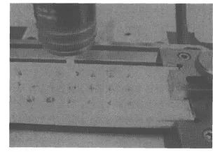
Tapping torque lubricity test (the test aluminum strip has been pre-drilled) value. The test result can be expressed as a simple torque value, or the effective percentage - the ratio of the average torque value of the reference fluid to the torque value of the fluid to be measured. The reference fluid and the fluid to be measured use the same tapping bit. L. DeChiffre believes that it is also necessary to evaluate the surface finish.
The percentage of tapping torque efficiency of the four metalworking fluids used for comparison. Two different speeds are used on 1215 steel. The data at the speed of 400r/min has little to do with the factory experience and the lathe test results. It is noted that the heavy load soluble oil and heavy load synthetic fluid appear to be worse than the medium load semi-synthetic fluid. At the speed of 1200r/min, the light load synthetic fluid, medium load semi-synthetic fluid and heavy load soluble oil were not much different from the expected values, but the heavy load synthetic fluid failed to tap. This may indicate that the friction lubricity is not good in the shaft and V-block test, and it is also not good in the tapping test. These data emphasize that the test conditions must be carefully selected in order to obtain reasonable and reliable conclusions. In addition to the composition of the processing fluid itself, many factors affect the tapping torque test results, including the quality of the tap, "cutting" tap or "forming" tap, the size of pre-cobalt and reamed holes relative to the size of the tap (sometimes expressed as thread percentage), metal alloy and metal hardness (metal samples vary greatly). Aluminum "cutting" tap and "forming" tap get different results. Note that forming tapping requires higher energy than cutting tapping, and can better reflect the difference of three liquids than cutting tapping. The cutting tap takes away the debris generated in the process of machining and generates thread by cutting the manhole wall. Unlike cutting tapping, forming tapping does not (or should not) produce chips. The forming tap extrudes the metal and forces the metal to flow into the required shape. 3. Metal deformation test There is no single laboratory test that can provide enough data information to evaluate metal forming lubricants, and people have reached a consensus. C. Wall, K. Dohda and N. Kawai and ASTM D4173 all adopt at least four laboratory test methods to study the different characteristics of metal forming and processing.
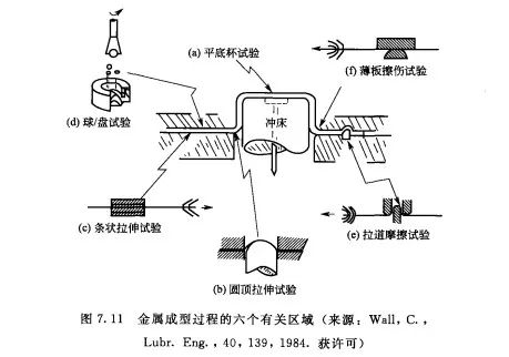
In the test, a lubricated metal plate or blank is squeezed by a blunt punch into a circular mold to form a cylindrical cup. The maximum tensile force in the test can be used as an indicator of lubricity. The other indicator is the ultimate tensile ratio or LDR, which is defined as the ratio of the largest successfully processed blank diameter to the punch diameter. The flat-bottomed cup test covers all aspects of metal forming, including friction and metal deformation force.
A lubricated metal plate is stretched by a round punch with sufficient blank holder force to prevent material slipping. The maximum tensile force and dome height are indicators of lubricity. This test studies the metalic properties of drawing, forming and processing. A strip tensile test, using a flat die and a metal strip to evaluate the moisture under pure sliding friction. Performance of the sliding agent. With the increase of clamping force, measure the corresponding tension. The friction coefficient can be calculated by dividing the average steady-state tension by twice the clamping force. The ball/disc wear test is an improved method of the four-ball machine test described previously. There are three plates in the metal cup to replace three static metal balls. There is also 5mL of lubricant in the metal cup. This improved four-ball machine test can evaluate both tensile lubricant and water-based rolling fluid. Raceways are often used to control the metal flow in the stamping process (especially in the automotive industry). Raceways help prevent wrinkling and keep walls even. The drawing simulator is used to evaluate the lubricant by drawing and lubricating the metal strip through a series of drawing channels and grooves (peaks and valleys). The metal is continuously bent and straightened, and then bent and straightened. Finally, draw a diagram of the distance between the pulling force and the moving distance. The same batch of metal strips shall be tested under the same clamping force. A reference oil is used as a standard for comparison. Each basic test described in this section is only one aspect of the whole metal forming process. Although the flat-bottomed cup tensile test may best simulate the stamping and stretching process of the production line, no single test can be expected to predict the site perfectly. The usual method is to select two or three tests whose results can be repeated, and the test process should include its most important process parameters. Only sheet test is realistic M. 4. Electrochemical method The mechanism of metalworking fluid as lubricant is that molecular thin layer is deposited on the metal surface to prevent chips, tools and workpiece from being welded together. If the molecular adsorption rate can be measured, then the effectiveness of a lubricant can be predicted. Naerheim and Kendig used the magnitude of electrochemical impedance as the quantitative method of this chemisorption, and found that there was a certain relationship between the magnitude of impedance and the metal cutting force for the three cutting fluids. They expect that this technology will save time and money than machining test.


